|
| |||
|---|---|---|---|

|
|
||
INTRODUCTION
A model of a system or component at an abstraction level higher than RTL in which the interface is defined in terms of transactions, rather than signals is called tranction level modelling. By abstracting out the details transaction level models run faster and can be written more easily. Transaction-level modeling is a high-level approach to model digital systems where details of communication among modules are separated from the details of the implementation of functional units or of the communication architecture. Communication mechanisms such as busses or FIFOs are modeled as channels, and are presented to modules using SystemVerilog interfaces. At the transaction level, the emphasis is more on the functionality of the data transfers - what data are transferred to and from what locations - and less on their actual implementation, that is, on the actual protocol used for data transfer. This approach makes it easier for reusability. Usually these tranctions are implimented using subroutiens. Systemverilog supports tranctional level modelling. The following example uses TLM in SystemVerilog.
Dut Specification:
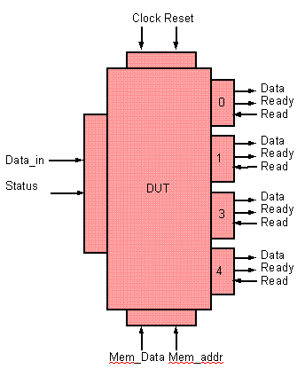
This DUT is a simple switch, which can drive the incoming packet to destination ports based on the address contained in the packet.
The dut contain one input interface from which the packet enters the dut. It has four output interfaces where the packet is driven out.

Packet format:
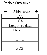
Packet contains Header, data and frame check sequence. Packet width is 8 bits and the length of the packet can be between 4 bytes to 259 bytes.
Packet header:
Packet header contains three fields DA, SA and length.
DA: Destination address of the packet. It is 8 bits. The switch drives the packet to respective ports based on this destination address of the packets.
SA: Source address of the packet from where it originate.
Length: This is the length of the data. It can be from 0 to 255.
Data: Data should be in terms of bytes. It can be between 0 to 255 bytes.
FCS: This field contains the security check of the packet. It is calculated over the header and data.

Configuration:
Dut has four output ports. These output ports have to be configure to a address. Dut matches the DA field of the packet with this configured port address and sends the packet on to that port. To configure the dut, a memory interface is provided. The address of the ports should be unique. It is 8 bits wide. Memory address (0,1,2,3) contains the address of port(0,1,2,4) respectively.
Interface Specification:
The dut has one input Interface, from where the packet enters the dut and 4 output interfaces from where the packet comes out and one memory interface, through the port address can be configured.
Memory Interface:
Through memory interfaced output port address are configured. It accepts 8 bit data to be written to memory. It has 8 bit address inputs. Address 0,1,2,3 contains the address of the port 0,1,2,3 respectively. If the DA feild in the packet matches with the confugured address of any port ,then the packet comes out of that port.
Input Interface:
The status signal has to be high when data is when packet is sent on to the dut it has to become low after sending last byte of the packet. 2 clocks gap should be maintained between packets.
Output Interface:
There are 4 ports, each having data, ready and read signals.
When the data is ready to be sent out from the port, dut makes the ready signal high indicating that data is ready to be sent.
If the read signal is made high when ready is high, then the data comes out of the data signal.
A model of a system or component at an abstraction level higher than RTL in which the interface is defined in terms of transactions, rather than signals is called tranction level modelling. By abstracting out the details transaction level models run faster and can be written more easily. Transaction-level modeling is a high-level approach to model digital systems where details of communication among modules are separated from the details of the implementation of functional units or of the communication architecture. Communication mechanisms such as busses or FIFOs are modeled as channels, and are presented to modules using SystemVerilog interfaces. At the transaction level, the emphasis is more on the functionality of the data transfers - what data are transferred to and from what locations - and less on their actual implementation, that is, on the actual protocol used for data transfer. This approach makes it easier for reusability. Usually these tranctions are implimented using subroutiens. Systemverilog supports tranctional level modelling. The following example uses TLM in SystemVerilog.
Dut Specification:
This DUT is a simple switch, which can drive the incoming packet to destination ports based on the address contained in the packet.
The dut contain one input interface from which the packet enters the dut. It has four output interfaces where the packet is driven out.

Packet format:
Packet contains Header, data and frame check sequence. Packet width is 8 bits and the length of the packet can be between 4 bytes to 259 bytes.
Packet header:
Packet header contains three fields DA, SA and length.
DA: Destination address of the packet. It is 8 bits. The switch drives the packet to respective ports based on this destination address of the packets.
SA: Source address of the packet from where it originate.
Length: This is the length of the data. It can be from 0 to 255.
Data: Data should be in terms of bytes. It can be between 0 to 255 bytes.
FCS: This field contains the security check of the packet. It is calculated over the header and data.

Configuration:
Dut has four output ports. These output ports have to be configure to a address. Dut matches the DA field of the packet with this configured port address and sends the packet on to that port. To configure the dut, a memory interface is provided. The address of the ports should be unique. It is 8 bits wide. Memory address (0,1,2,3) contains the address of port(0,1,2,4) respectively.
Interface Specification:
The dut has one input Interface, from where the packet enters the dut and 4 output interfaces from where the packet comes out and one memory interface, through the port address can be configured.
Memory Interface:
Through memory interfaced output port address are configured. It accepts 8 bit data to be written to memory. It has 8 bit address inputs. Address 0,1,2,3 contains the address of the port 0,1,2,3 respectively. If the DA feild in the packet matches with the confugured address of any port ,then the packet comes out of that port.
Input Interface:
The status signal has to be high when data is when packet is sent on to the dut it has to become low after sending last byte of the packet. 2 clocks gap should be maintained between packets.
Output Interface:
There are 4 ports, each having data, ready and read signals.
When the data is ready to be sent out from the port, dut makes the ready signal high indicating that data is ready to be sent.
If the read signal is made high when ready is high, then the data comes out of the data signal.
Index
Introduction
Rtl
Top
Interface
Program Block
Environment
Packet
Configuration
Driver
Reciever
Scoreboard
Report a Bug or Comment on This section - Your input is what keeps Testbench.in improving with time!

Introduction
Rtl
Top
Interface
Program Block
Environment
Packet
Configuration
Driver
Reciever
Scoreboard
Report a Bug or Comment on This section - Your input is what keeps Testbench.in improving with time!

